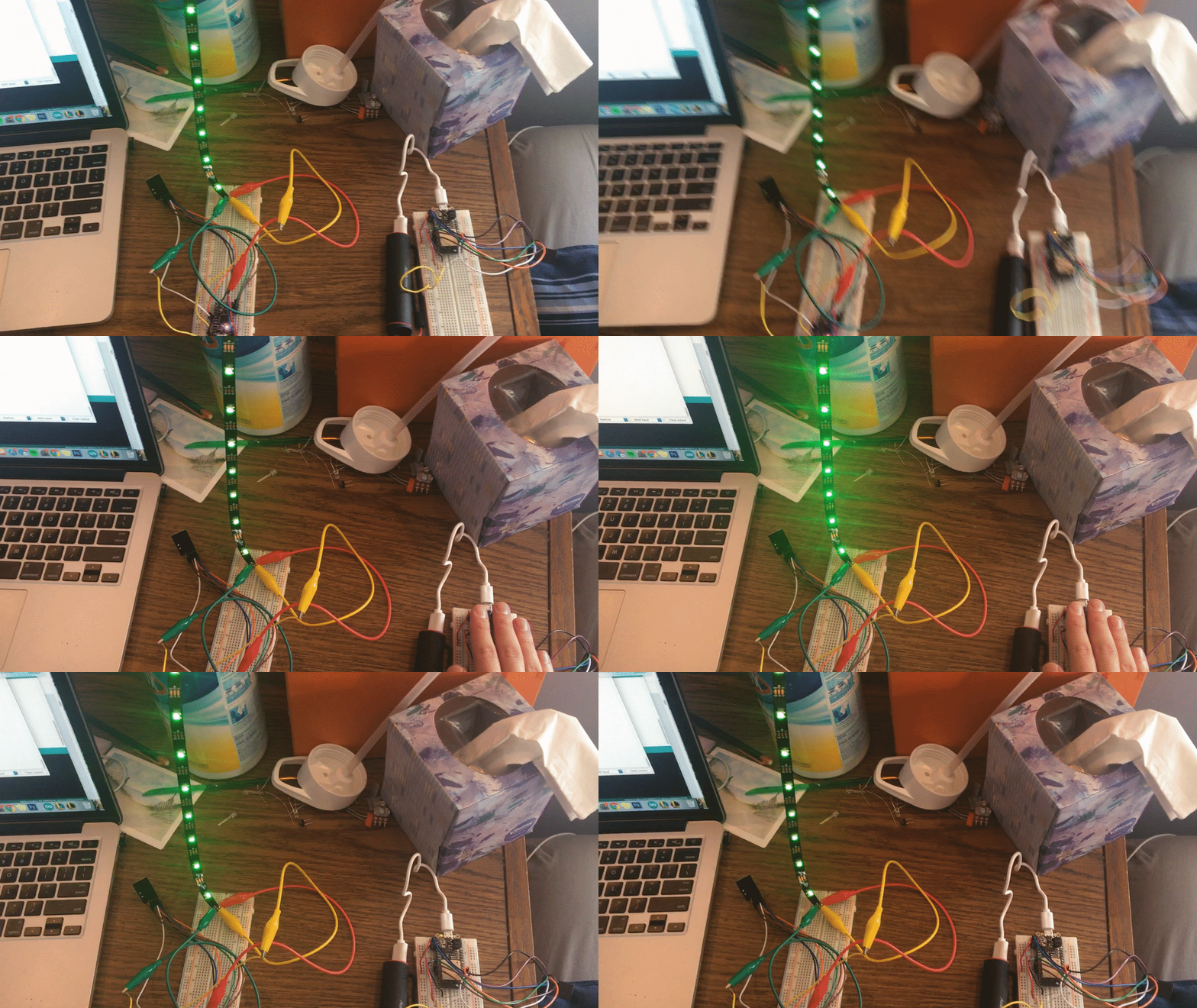
The Assignment: Demonstrate 2 microcontrollers communicating over wired or radio connection.
Materials:
My Project:
For this assignment, I decided to create a light level monitor using a photoresistor that then would modify the light level of another light source elsewhere via radio communication. First, I had to get the feather esp32 huzzah microcontroller effectively sending a signal from the nRF24L01 radio. To do this, I used the tutorial that can be found here. I attached the pins to the huzzah as specified in this tutorial. Then, using the sample code snippet from the course tutorial that can be found here, I loaded the code into my Arduino software. I simply modified the pin numbers for the Huzzah board.
Uploading the code to the feather took a little bit more work. I followed the tutorial here, which contained a link for the SiliconLabs USB converter software and also the board manager for the feather esp32. After downloading these necessary pieces of software, I uploaded the send code to the Huzzah. Upon opening my serial monitor, the code worked! While there was no radio receiving the signal and thus it printed “failed,” the serial also noted that it was sending incremented numbers successfully.
My next step was getting the ItsyBitsy to receive the signal. The above tutorial with the radio pin specifications also has information on how to rig up the pins for the ItsyBitsy. I did this, loaded in the sample code, and got the signal received in the serial monitor once I attached the huzzah to the power source with another microUSB cable.
Next, I needed the Huzzah to read the input of the photoresistor. To do this, I created a simple circuit with the photoresistor being connected from the analog pin to ground and with the analog pin being attached to the 3V pin through a 10k resistor. The setup can be seen below:

Next, I wanted to create a function that would allow me to cycle through inputs for my three primary output adjustments: hue, brightness, and number of lights. To do this, I added a button circuit and created a variable to store which of the three variables I was changing at a given time. An example of the button circuit can be found in my Week 4 documentation. The code I wrote scales the variable input of the potentiometer into different variables which then affect the outputs of the light strip.
I then added the following lines of code to the send file in Arduino, ensuring that it was now sending the data from the photoresistor by checking the serial output.
      void loop() {
        data = analogRead(A3);   // read the input on analog pin A3
      }
Finally, I added the following lines of code adapted from the NeoPixel "sample" example to my “receive” Arduino file to take the data received and convert it into a variable brightness for the LED strip, which can be found alongside the finished product below:
        #include
        // Which pin on the Arduino is connected to the NeoPixels?
        #define PIN 12 // On Trinket or Gemma, suggest changing this to 1

        // How many NeoPixels are attached to the Arduino?
        #define NUMPIXELS 10 // Popular NeoPixel ring size

        Adafruit_NeoPixel pixels(NUMPIXELS, PIN, NEO_GRB + NEO_KHZ800);
        void setup() {
          // put your setup code here, to run once:
          pixels.begin(); // INITIALIZE NeoPixel strip object (REQUIRED)
          pixels.clear();
        }

        void loop() {
for(int i=0; i 